Progressive cavity pumps are essential components in various industries, effectively moving fluids with varying viscosities. Understanding their diagrams helps in grasping their operation and maintenance. This guide will break down the key elements of progressive cavity pump diagrams, making it easier to visualize their function.
What is a Progressive Cavity Pump?
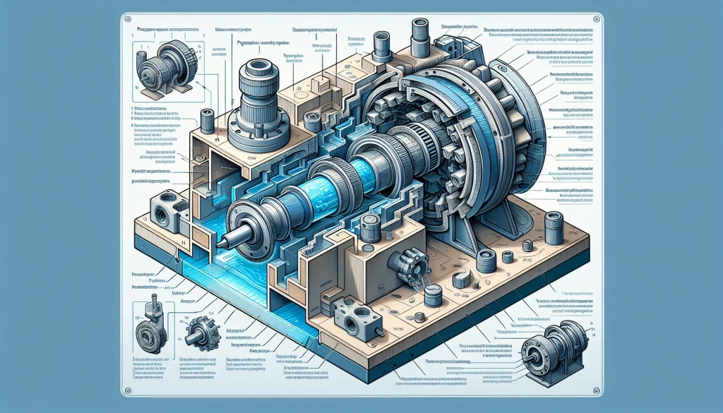
A progressive cavity pump consists of a helical rotor and a stator that work together to create a continuous flow of fluid. The rotor turns within the stator, forming cavities that transport the fluid from the inlet to the outlet. This design allows for the efficient handling of thick, viscous materials.
Key Components of the Diagram
- Rotor
- The helical component that rotates within the stator.
- Creates a vacuum that draws fluid into the pump.
- Stator
- The stationary part that surrounds the rotor.
- Designed with a double helix that complements the rotor’s shape, allowing fluid to be moved through the cavities.
- Inlet
- The entry point for fluid.
- Typically located at the bottom of the pump.
- Outlet
- The exit point where the fluid is discharged.
- Positioned at the top of the pump.
- Drive Shaft
- Connects the rotor to the motor.
- Transfers mechanical energy to rotate the rotor.
- Bearing System
- Supports the rotor and allows it to rotate smoothly.
- Ensures the longevity and efficiency of the pump.
Understanding the Flow Path
The diagram of a progressive cavity pump illustrates the flow path of the fluid. As the rotor turns, it creates a series of cavities that expand and contract, moving the fluid through the stator. This continuous motion allows for a steady and uniform flow, essential for processes that require precise fluid handling.
Benefits of Progressive Cavity Pumps
- Versatility: Can handle a wide range of fluids, including slurries and viscous liquids.
- Consistent Flow: Provides a smooth and continuous flow, minimizing pulsation.
- Self-Priming: Capable of drawing fluid into the pump without external assistance.
Maintenance Tips
Understanding the diagram also aids in proper maintenance. Here are some essential tips:
- Regular Inspection: Check for wear and tear on the rotor and stator.
- Seal Checks: Ensure that seals are intact to prevent leaks.
- Lubrication: Keep the bearings properly lubricated for optimal performance.
- Monitor Flow Rates: Regularly check that the flow remains consistent.
Conclusion
A solid grasp of progressive cavity pump diagrams is crucial for anyone involved in their operation or maintenance. By understanding the components and flow path, users can enhance their efficiency, troubleshoot issues, and ensure longevity. Whether you are new to the industry or looking to refine your knowledge, this guide serves as a valuable resource in mastering the intricacies of progressive cavity pumps.